Obsticle Navigating ROS2 Controlled Robot
Project Constraints
The project had to use the Create 3 robot provided for the assignment
All robot commands had to be sent through Airtable from a team member in another room
Any camera system could be used to monitor the robot’s position in the course (e.g., a phone camera over Zoom)
Any additions to the system had to be designed from scratch, pre-made files or designs were not allowed
The goal of this project was to explore how APIs enable remote robot control over the internet and how the ROS 2 framework uses nodes to communicate and share information within a robotic system
Prototyping and Understanding Components
Prototype Design Process:
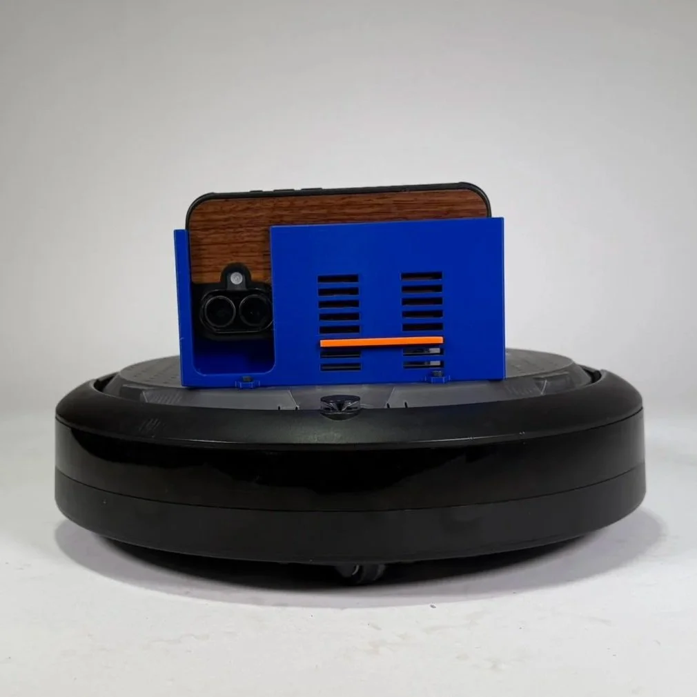
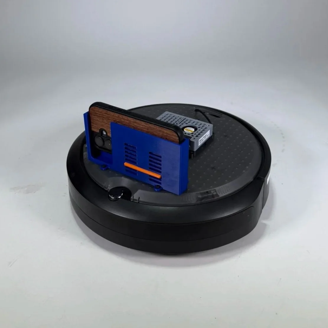
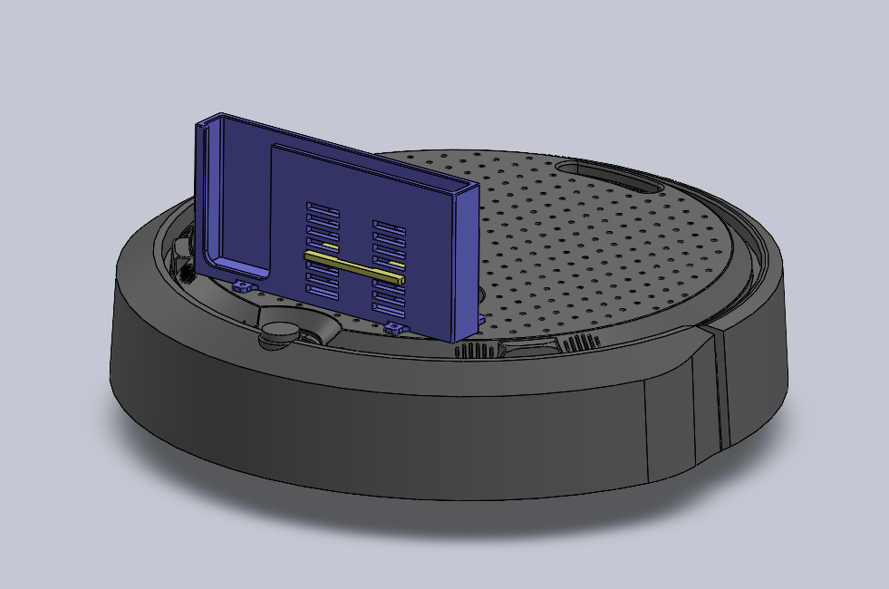
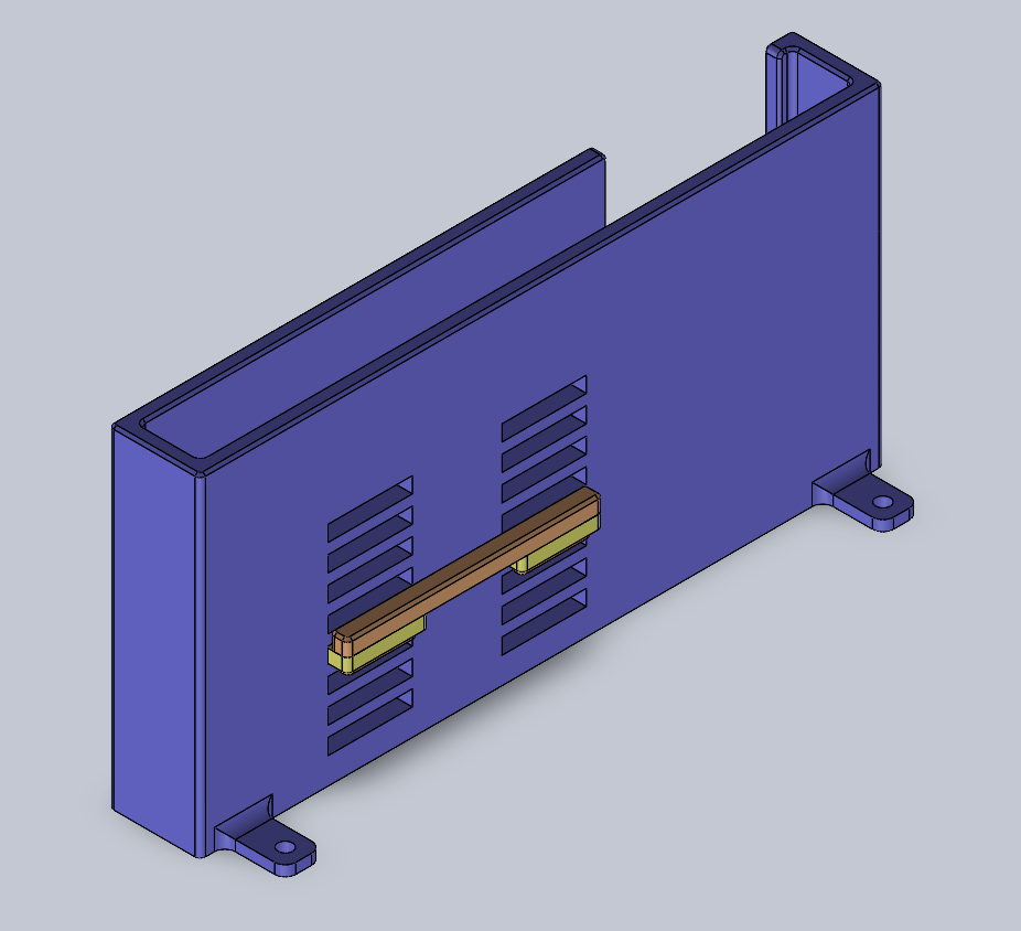
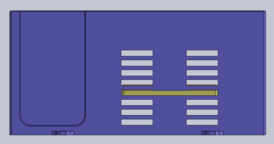
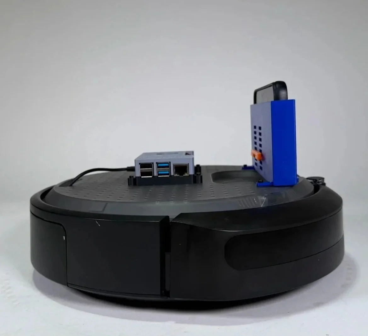
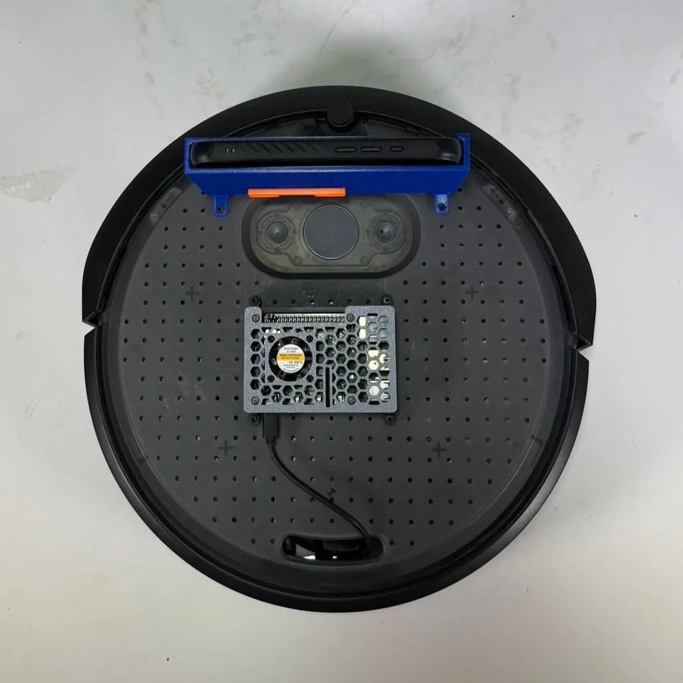
3D printed custom adjustable phone stand mounted on the robot provided a live video view of the robot’s position
Designed to fit screws that seamlessly fit with the create 3’s screw hole pattern
The orange tab can be removed and repositioned to test a variety of heights for the phone to sit at for optimal field of view
Understanding the Electrical Components Used:
The system used a Raspberry Pi 4 as the main computer, connected to the iRobot Create 3, which is designed to work with Robot Operating System 2 (ROS2)
The Raspberry Pi retrieved movement commands from Airtable and translated them into robot motion using ROS 2
The Create 3’s motors and built in sensors allowed it to execute those commands and navigate through the course
Code and Programming
How the system works:
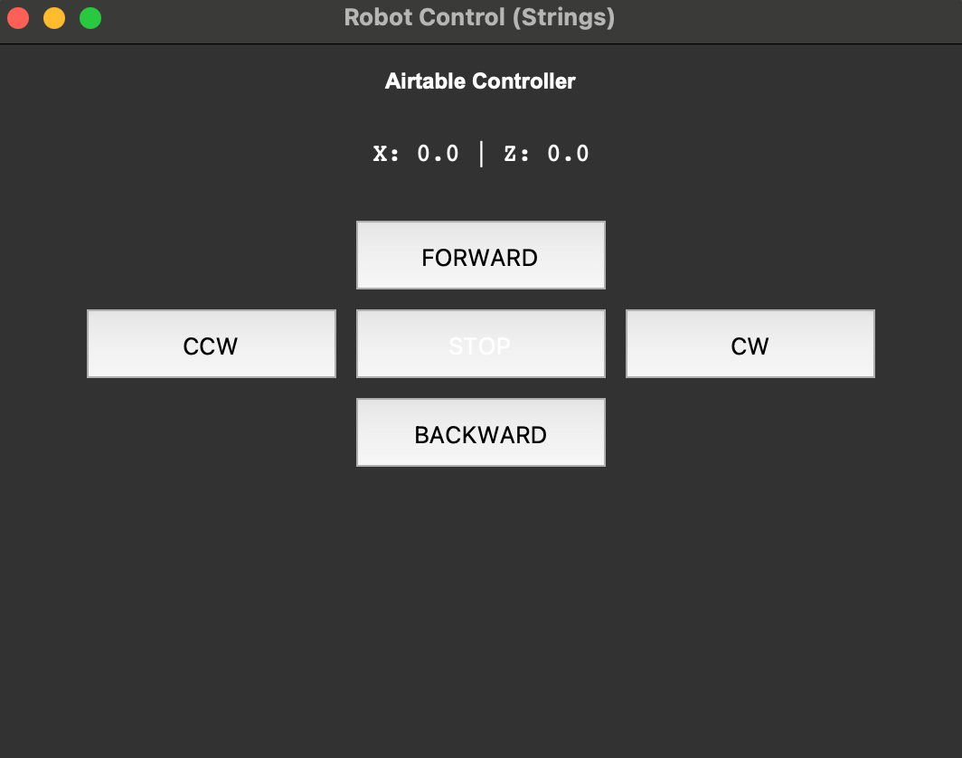
A user controls the robot through a Python GUI on a laptop with buttons for forward, backward, turning, and stopping
When a button is pressed, the program sends a request through the API to update velocity values in Airtable
A Raspberry Pi 4 connected to the robot continuously reads those values from Airtable
A node running in ROS2 converts the values into robot movement commands
The commands are published to the robot, and the iRobot Create 3 executes the motion using its motors
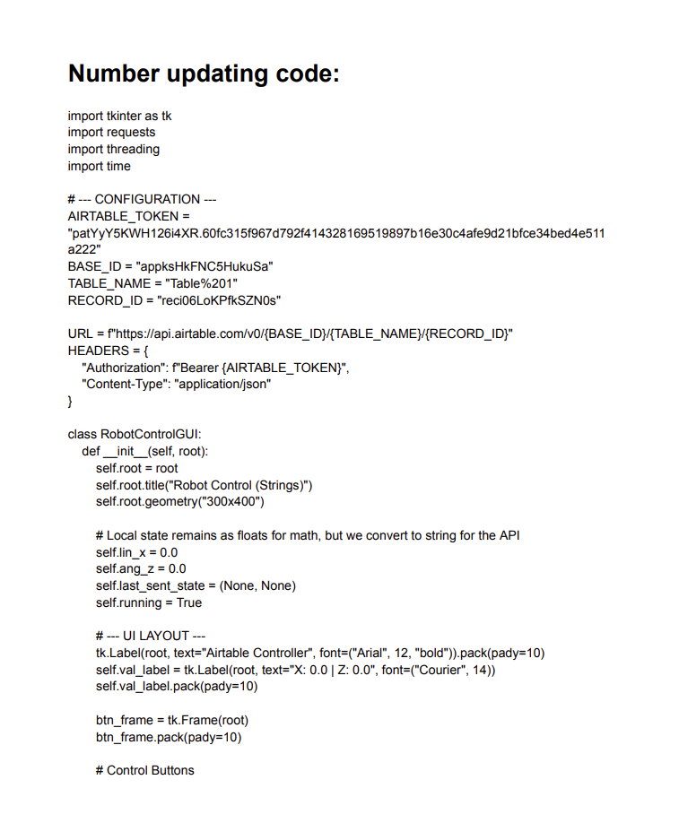
How the code works:
The GUI program updates the robot’s linear velocity (forward/backward) and angular velocity (rotation) by sending a PATCH request to Airtable
These values range from -1, 0, or 1, representing direction and movement magnitude
A ROS 2 node on the Raspberry Pi repeatedly sends a GET request to retrieve the latest velocity values from Airtable
The node converts those values into a Twist message, which is the standard ROS format for robot movement
The message is published to the /cmd_vel topic, where the robot reads the values (linear.x and angular.z) and moves accordingly
Click to read the code
Final Design and Demonstration
Our robot was able to reliably take inputs from the GUI and move as expected
The movement was relatively smooth, though turning could have been smoother
It would be interesting to explore using arrow keys instead of buttons for movement, as that might feel more intuitive
The robot successfully completed the obstacle course, which included multiple sponge blocks, chairs, and trash cans as stationary obstacles, as well as two moving obstacles( a broom following an arcing pattern and a trash can moving back and forth)
Field of view was certainly a limitation, especially since the camera only showed what was directly in front of the robot
Using just the phone for visuals limited our perspective, and had we had access to the Create 3’s built-in sensors, we might have been able to better visualize the 3D space for more precise movement
Video of Demonstration
Reflection and Takeaways
It was interesting learning about APIs and seeing how much of the internet, and the systems we interact with daily, rely on them to function
The ROS 2 system was relatively intuitive, but it was still a fun challenge to understand a new framework and integrate our code and concepts with it
Designing the phone stand was fun, and the adjustable design helped reduce the number of prints and the time required to create a working prototype