Teardown & Analysis of
Hammerhead Oscillating Multi-Tool
As an assignment for ME40 Engineering Design, I was asked to work with two partners to analyze the Hammerhead 2.2-Amp Oscillating Multi-Tool. The goal for the project was to understand how the oscillating multi-tool worked and how each component impacted the functionality of the tool.
As a group we completed:
Research on users
Task analysis, decomposition table, and function structure
Teardown and exploded view
CAD model of the deconstructed tool
This information could be used to improve product design, optimize usability, enhance user instructions, support reverse engineering, enable digital prototyping, and streamline manufacturing and assembly.
Initial Research
What is the multi-tool used for:
Detailed sanding, sawing, scraping, and grout removal
2.2 amp motor running on AC power
Designed to be ergonomic, versatile, powerful, and intuitive
Who is expected to use the tool:
Woodworking professionals
Home repair enthusiasts
Plumbers
Electricians
Used in an open and clean environment such as a woodshop, garage, or shed
What is the user experience:
Instructional and “quick start” videos are available on Youtube
With the tool comes a detailed user instruction manual that offers safety information, preparation, operating instructions, and care and maintenance information
Generally good reviews on Amazon with 4.5/5 stars as customers mostly seem to find the rotary tool functional and easy to use while being good value for the price, but having mixed opinions on the build quality and accessories


Initial User Experience
Assembly Process

First Use Process
Problems/difficulties found along the way:
Attachment orientation – Attachments can be installed in either direction posing a safety concern due to unclear instruction visuals
Default saw speed – saw speed starts at level 6 (highest setting) out of the box, which can be dangerous if unknown
Hand placement uncertainty – lack of guidance on where users should place their hands on the tool for safe operation
Ergonomic concerns – the tool does not feel ergonomic leading to uncomfort and safety concerns
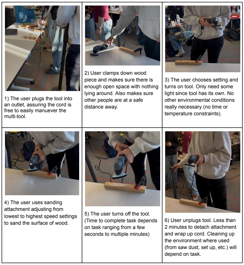
Task Analysis
Practicing Observation:
We asked a new user to sand a piece of wood as a simple, but real application of the oscillating multi-tool. We recruited a friend who had not used the tool to complete this task and observed how they opened and used the product. As they used the multi-tool, they talked through their thoughts of how they were approaching the task.
We recorded the process and each group member performed their own task analysis, after which a combined task analysis was created shown on the right.

Click on task analysis to open in another tab
External Product Overview
External Design Choices and Effects
What affordances allow for proper usage?
Power switch – Designed to slide forward and backward, indicating on/off
Dial - Allows for intuitive turning to adjust speed
Attachment slots – Clearly guide the correct orientation of attachments for secure installation
Allen wrench holder – Affords sliding tool through openings
Sloped handle – Naturally guides the user’s grip for better control and comfort
How do they hold it?
Two hand grip – One hand on the middle section for stability, the other on the back for control
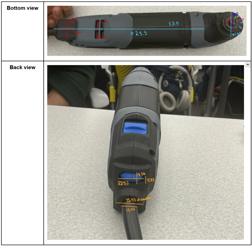
Dimensions and Photos

What visual cues does the user have?
Tapered middle section – Indicates proper hand placement for stability
Attachment tabs – Indicate where and how attachments should be placed
Clearly marked buttons/switches – Intuitive placement and enhances usability. Colors improve visibility for quick identification
Numbered settings dial – Provides a clear reference for speed and power adjustments
How do they make adjustments?
Attachment changes – Uses allen wrench to swap attachments
Power and speed adjustments – Controlled via the turnable settings dial
Understanding how the Multi-tool Works
Operation of Internal Components
Interesting takeaways from internal motion:
How the sliding motion to turn the tool on/off used a plastic arm to flip a single pole switch on/off
Seeing and understanding how the carbon brushes are used to power the universal motor
Understanding how the rotational motion converted by the universal motor is converted to oscillating motion
Demystifying how the dial affects the speed of the oscillations (electrical rather than mechanical)
Function Structure of Sanding Process
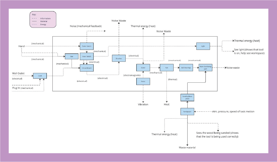
Click to open function structure in another tab
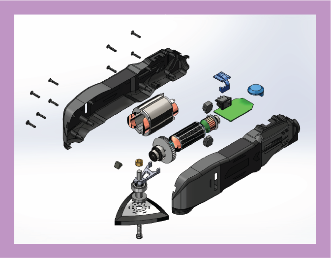
Breaking Down the Tool to Simpler Parts
Exploded View
How do the pieces come together:
Rotor & Stator: The rotor (11) fits inside the stator (10), which is placed in the case with the fan at the front.
Oscillating Mechanism: The oscillating part (6) locks into the front grooves and connects to a rotor bearing, converting rotation into oscillation.
Commutator & Brushes: The commutator bar connects to spring-loaded carbon brushes (12), which are wired to the circuit board (13) at the back.
Switches & Controls: The circuit board houses all wiring, with the dial (19) attached and the outer switch (16) pressing the rocker switch (18).
Fasteners: Case screws (2) secure the housing, while the oscillating part screw (9) ensures proper attachment connections.
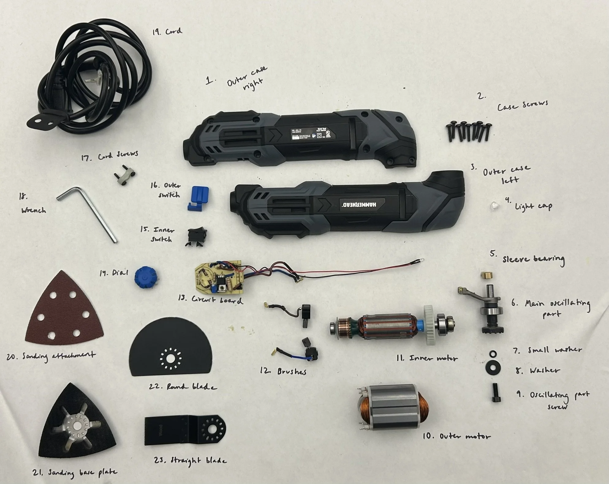
Decomposition Table and Dissasembly Process

Click to open FULL decomposition table and disassembly process in another tab
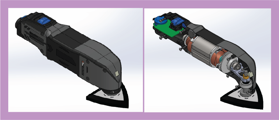
CAD Model and Exploded View
Tool breakdown and 3D modeling:
Broke the multi-tool down to its most basic parts with the limited tools we had available and modeled each part in SolidWorks to create a full 3D modeled version of the tool
Standard components (e.g., screws, bearings) were sourced from McMaster-Carr, while custom parts required modeling from scratch
Created an exploded view of our modeled reconstruction of the tool
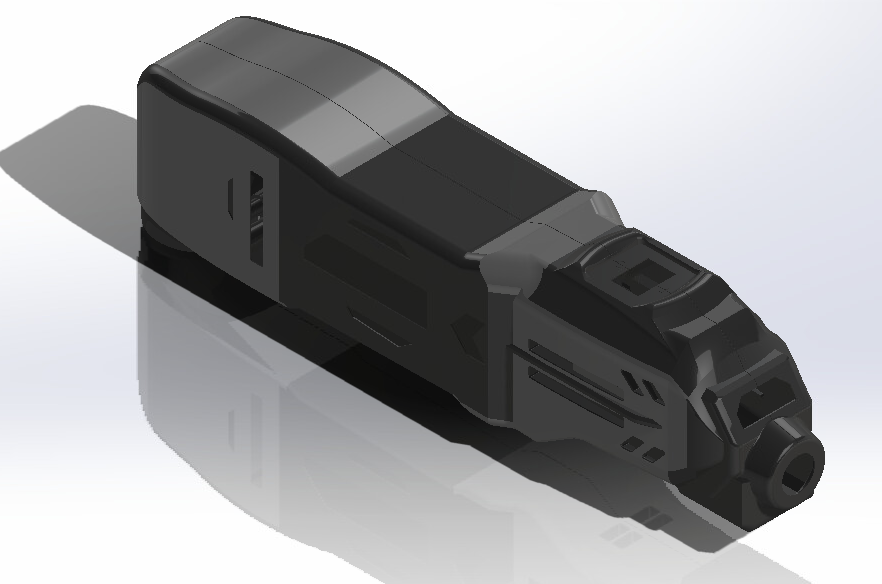
My contribution to the CAD model:
Took on the task of modeling the complex, injection-molded case
Used a combination of methods, including the “Sketch Picture” tool and precise measurements, to closely replicate the original case in the model
Because the case was the most difficult part to model, it was the only part I created, but I aided the team in creating the full assembly and the exploded view as well
Multiple Views of FULL CAD Assembly
Click to open CAD photos in another tab
Isometric view without lines

Back view with lines
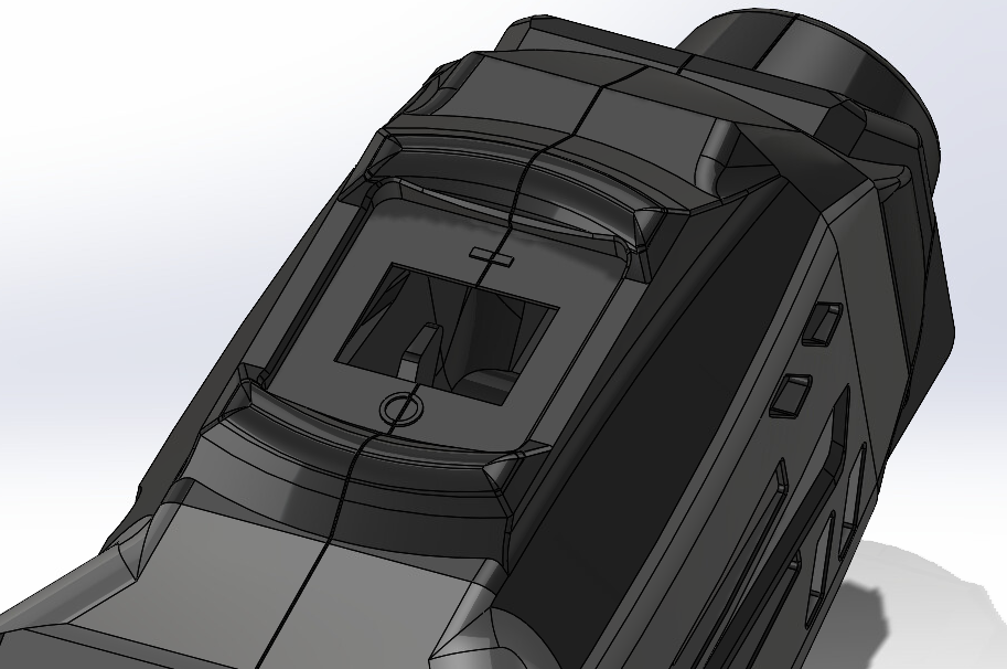
On/Off button view with lines
CAD Exploded View

Click to open exploded view in another tab