IR Line Following Robot
Quick Summary:
Built a two-wheeled robot that used IR sensors and a PID control system to follow a set path, with the PID continuously adjusting each motor to keep the robot on track
Worked with a partner to design and build everything from scratch in a week: laser cutting and 3D printing the chassis, wiring up a protoboard, and programming a Raspberry Pi to tie it all together
Building and tuning the PID system hands-on gave me a concrete, physical intuition for how they work, which made it much easier to understand the theory when it came up later in other coursework
Understanding the Challange
Project Constraints
Implement line-following behavior using a minimum of three IR reflectance sensors (cameras and alternative sensing modalities were not permitted)
Follow one of two predefined track layouts, one of which is designed with tight turns, intersections, and 90-degree turns
Design and fabricate a custom robot chassis from scratch
The robot had to be constructed and demonstrated within one week
Additional Self-imposed Constraint
Fully implement a 5+ sensor array that does PID control with well-tuned gains
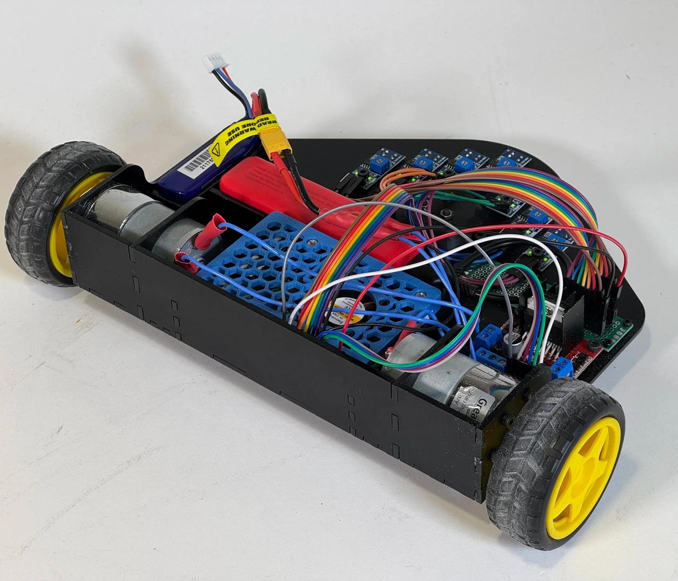
Use LiPo battery for power, so the robot is untethered
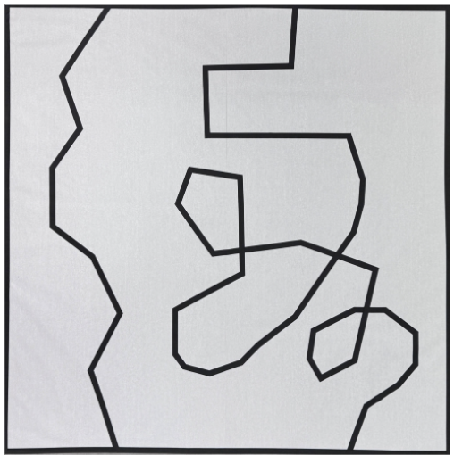
Easy and difficult pathway options
Prototyping and Understanding Components
Prototype Design Process:
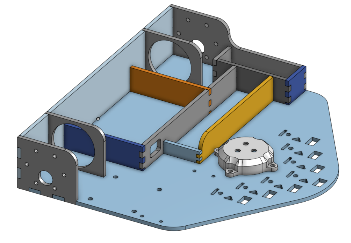
Designed the layout of the laser-cut chassis in CAD, along with 3D printed parts to integrate electrical and mechanical components
Used simple finger joints using Onshape’s built-in tools to improve structural rigidity and simplify assembly
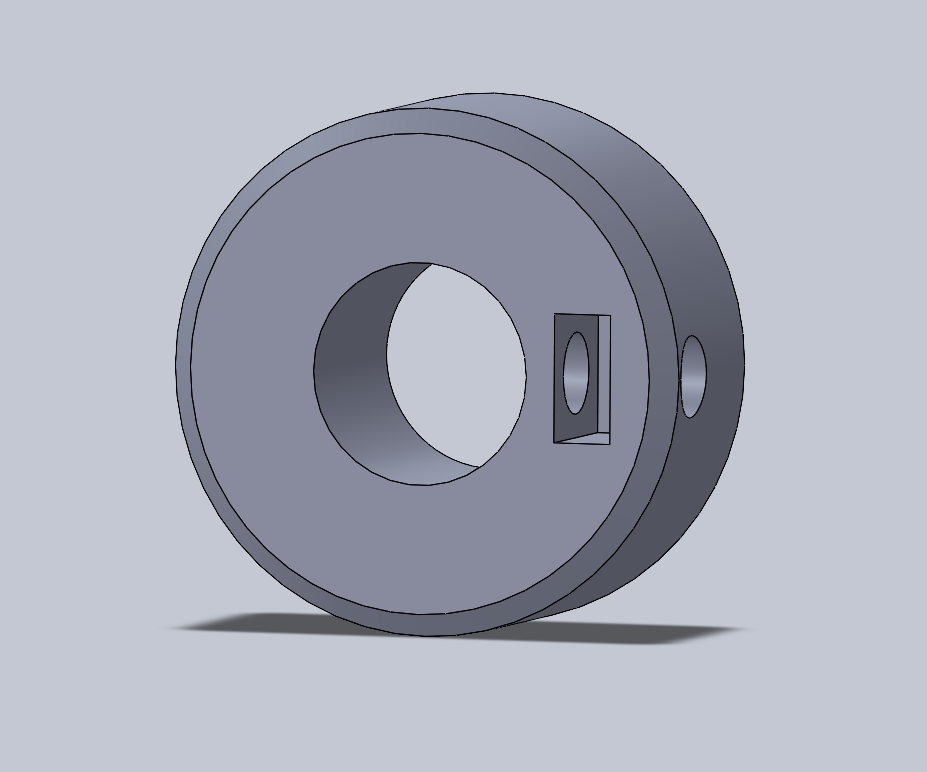
Designed a custom shaft collar using a captive nut to securely mount the wheels to the DC motors
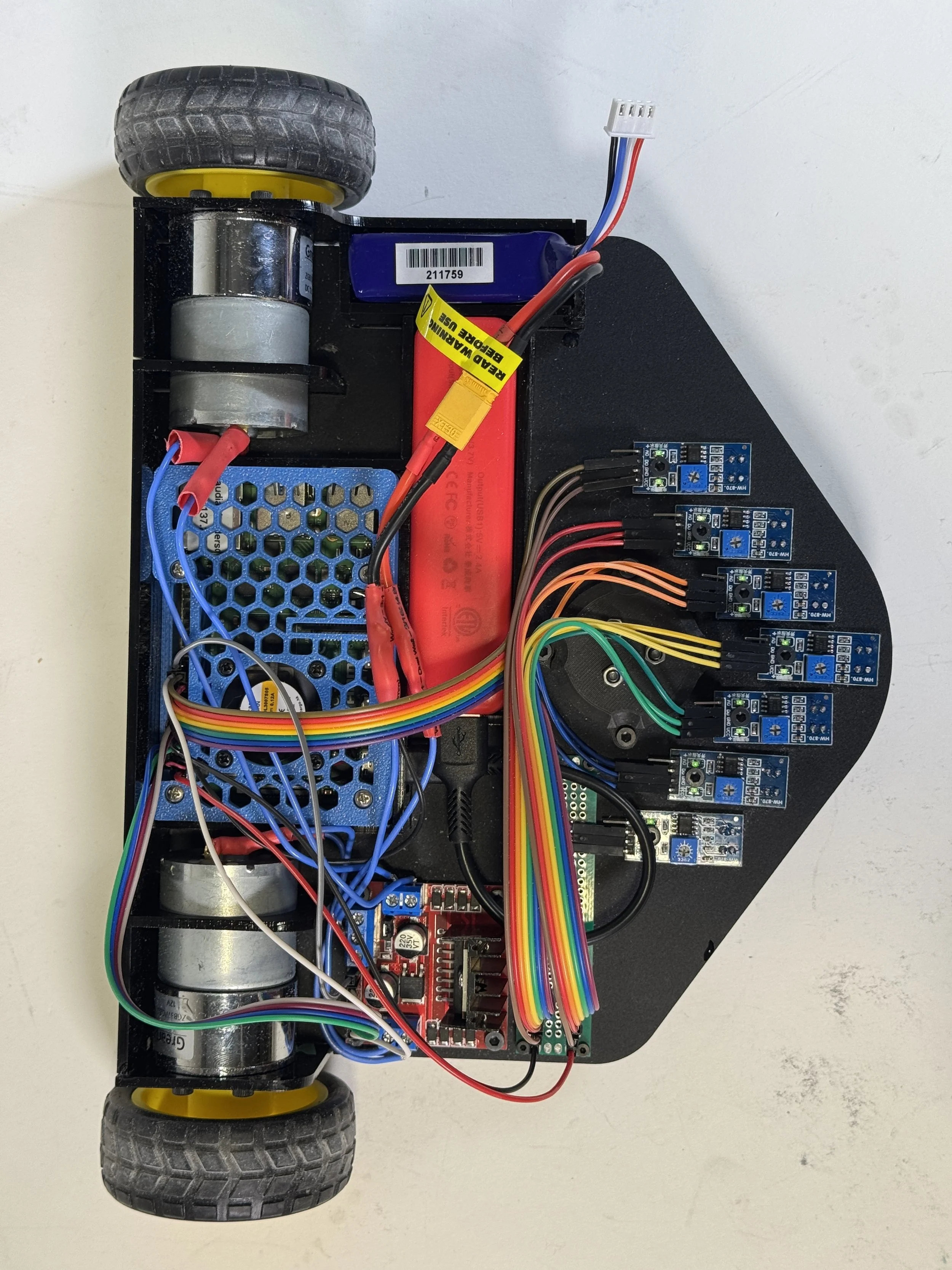
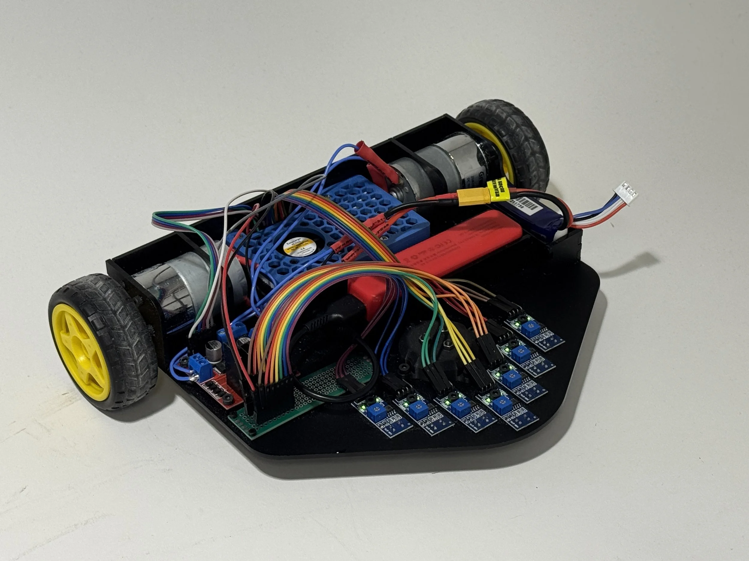
Understanding the Electrical Components Used:
The robot was built around a Raspberry Pi 4, along with a motor driver to power two DC motors
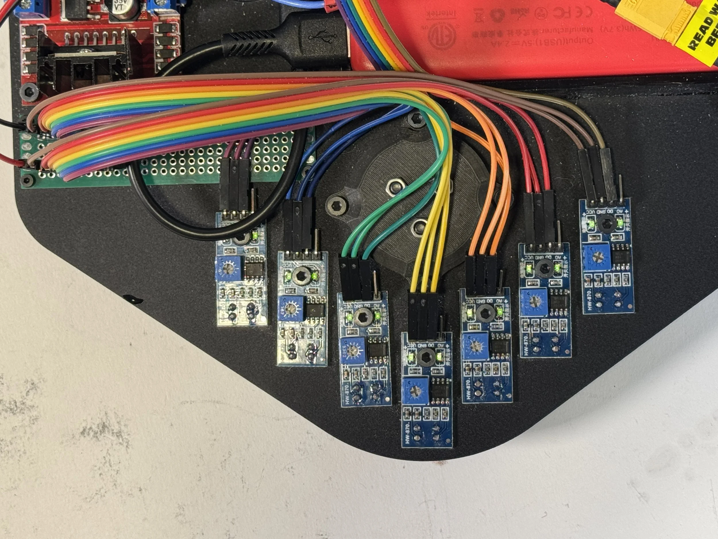
Integrated a 7-TCRT5000 IR array arranged in an arrow pattern to maximize the spatial resolution and hopefully improve line detection
Emits infrared light toward the ground and measures the amount reflected back, allowing it to distinguish between light and dark surfaces (e.g., detecting a black line on a white background for line following)
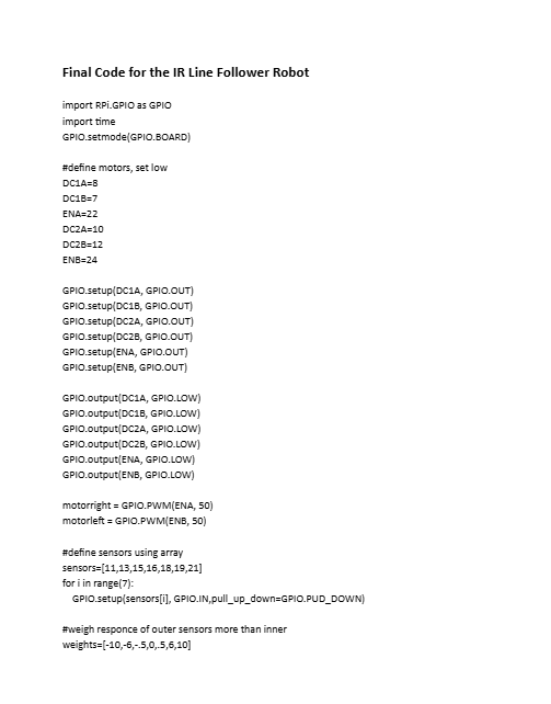
Code and Programming
What Does the Code Do
Configures the Raspberry Pi’s GPIO pins to control two DC motors and read data from a 7-sensor TCRT5000 IR array
Continuously reads the IR sensors to determine the robot’s position relative to the line
Calculates how far the robot is from the center of the line using a weighted average of the active sensors
Uses a PID control algorithm to compute a correction value based on this error
PID controller continuously calculates how far the robot is from the line (proportional), accounts for how long it has been off the line (integral), and predicts how quickly that error is changing (derivative), then combines these three terms to adjust the motor speeds and keep the robot centered on the line
Adjusts the speed and direction of each motor in real time so the robot smoothly steers back toward the line
Repeats this process rapidly, allowing the robot to track the line accurately and respond quickly to curves and disturbances
Click to read the code
Final Design and Demonstration
The robot successfully went through both the easier and more challenging tracks, reliably passing through intersections and tight corners
A full PID control system was implemented, which made for smooth, controlled driving. However, to get consistent tracking required reducing the robot’s speed
The arrow-shaped 7-sensor shape proved to be highly effective, offering precise line localization
Seeing other people’s designs, it would have been smart to line up the wheels closer to the sensors for more immediate responses to the readings
Reflection and Takeaways
Very happy and proud of how this project came out
My main takeaway was gaining a deeper understanding of how a PID control system works and how it smooths and maximizes sensor readings when designing moving systems
I had a lot of trouble while writing code for the robot, trying to write a function to interpret intersections and how to respond. But by discussing the problem with my teammate, we together were able to find a better and simpler solution. A nice reinforcment of how important collaboration and bouncing ideas off one another is so crucial in the prototyping and design process