Camera Line Following Robot
Project Constraints
The provided Raspberry Pi Camera 3 had to be used as the primary sensor for line detection and path tracking, with a Raspberry Pi acting as the brain of the robot
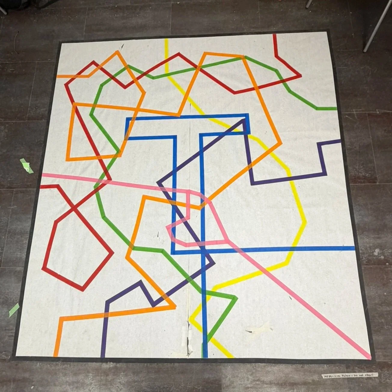
The robot was required to autonomously follow one of the 7 colored tape pathways on the ground, but was given the choice of which line to complete
A new chassis had to be fully designed and fabricated from scratch
The project timeline was limited to two weeks, ending in a live demonstration
Additional Self-imposed Constraint
Wanted the robot to be able to complete all 7 colored lines
Prototyping and Understanding Components
Prototype Design Process:
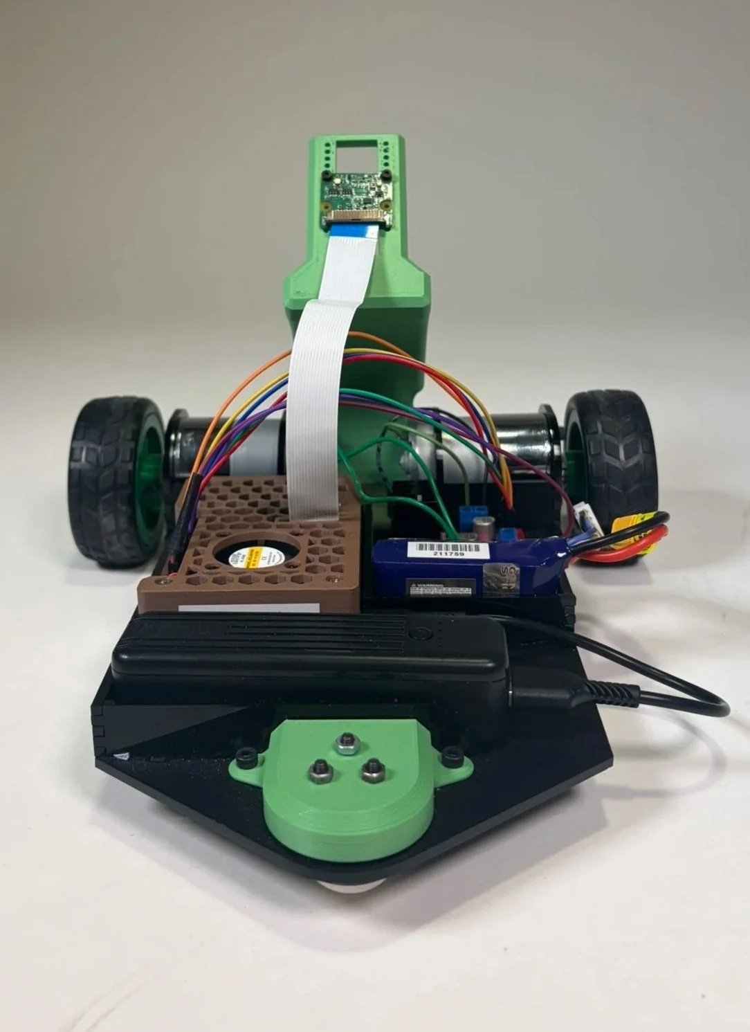
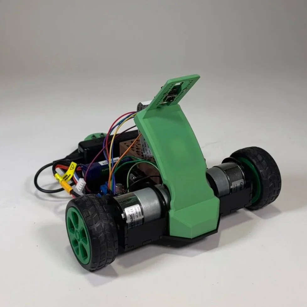
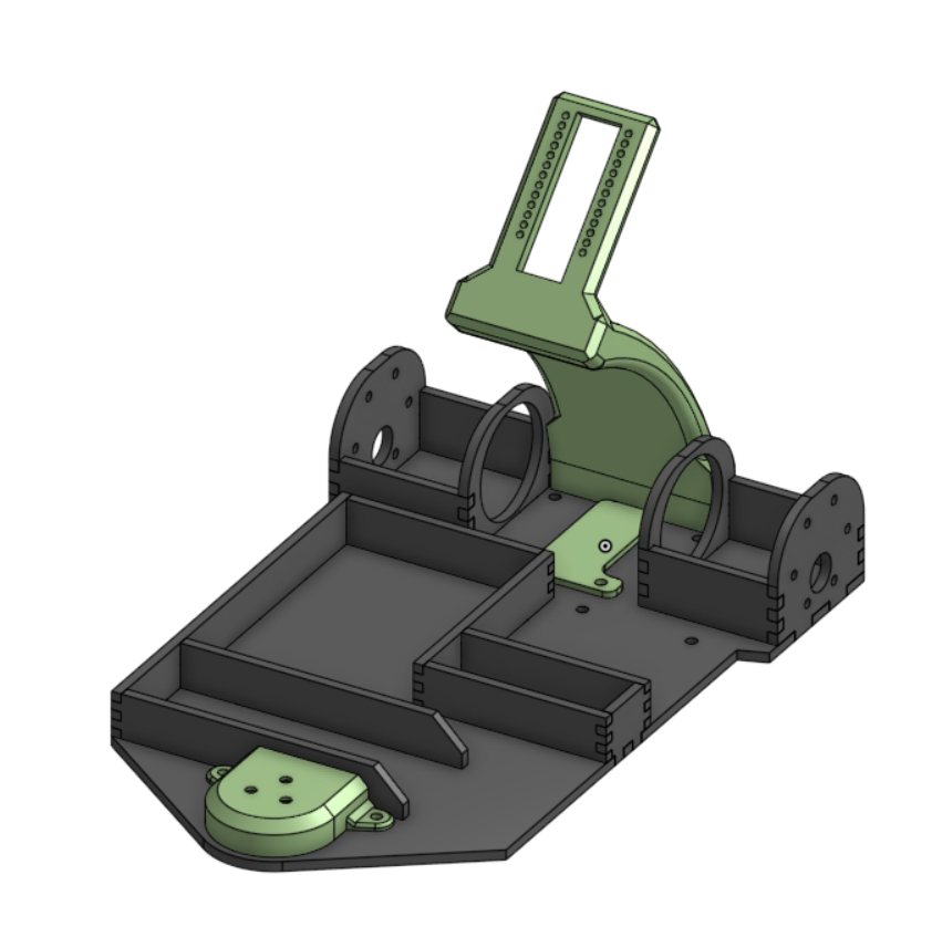
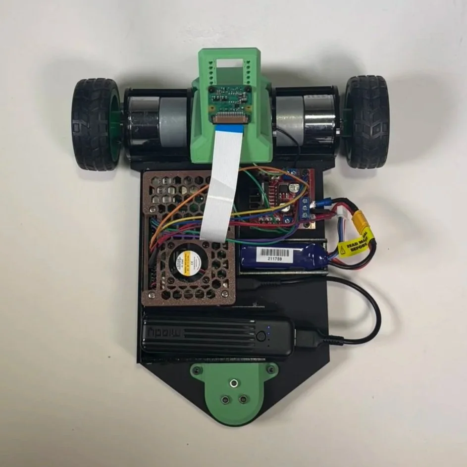
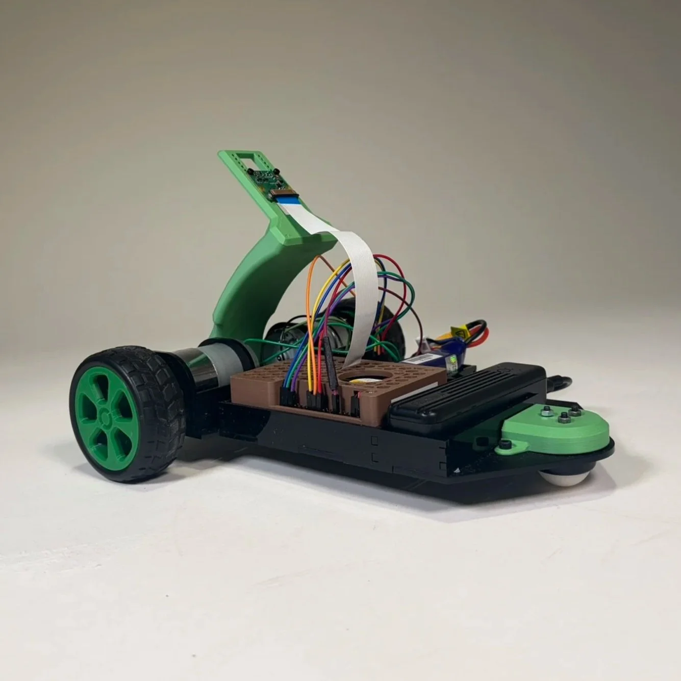
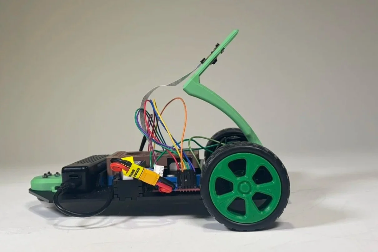
Designed the laser-cut chassis layout in CAD, along with 3D printed parts to mount the caster wheel and position the camera at a 45-degree angle to maximize the field of view in front of the robot
Used simple finger joints and short walls to hold components in place and to simplify assembly
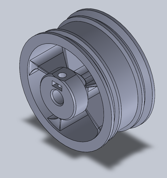
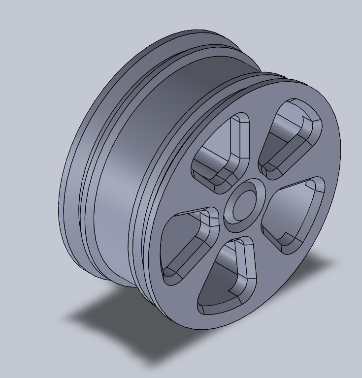
Adjusted an existing wheel design by remaking the hub with a built-in shaft collar and captive nut to securely attach the wheel to the motor shaft
Understanding the Electrical Components Used:
The robot was built around a Raspberry Pi 4, along with a motor driver to power two DC motors
The Raspberry Pi Camera Module 3 was straightforward to integrate and provided 12 MP resolution, autofocus, and up to 50 fps capture, supporting reliable real-time vision for line following
Code and Programming
What Does the Code Do
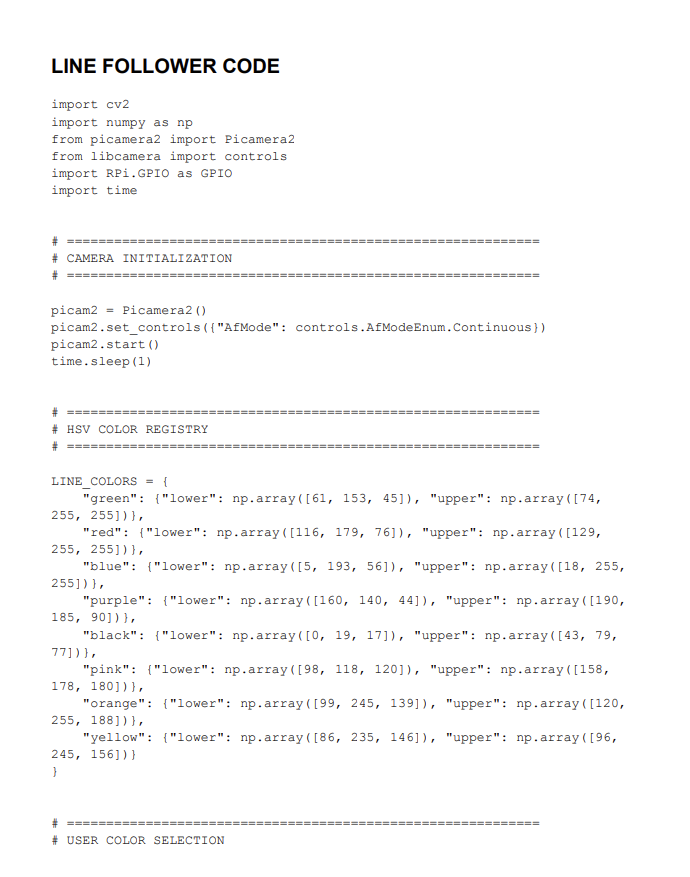
Line Follower Code
Captures and processes real-time camera footage using OpenCV to detect and track a user-selected colored line in HSV space
Computes line position error and applies a PID controller to dynamically adjust motor speeds for smooth, stable steering
Controls DC motors using PWM signals and includes a recovery routine that spins the robot to reacquire the line when tracking is lost
Displays live debugging views of the camera feed and detection mask for tuning and validation
Calibration Code
Allows users to collect HSV values directly from the camera feed by clicking on the target line
Automatically computes and outputs optimized HSV threshold ranges for color detection
Click to read the code
Final Design and Demonstration
Our robot was able to reliably complete 5 of the 7 tracks
Unable to complete the blue track because of the tight and quick 90-degree turn
Unable to complete the yellow track as the hues were too similar to orange, and the robot would consistently go off the yellow to orange pathway
A PID control system was implemented, which made for smooth driving relatively consistently on the provided line
The elevated, angled view of the camera provided an ideal setup, as we could see directly up to 5 inches in front of our robot, while also lining up the camera with the wheels
Some groups had shorter distances between their wheels and the camera, which could have been conducive to better line tracking capabilities and a more immediate response
Green Line
Purple Line
Orange Line
Red Line
Reflection and Takeaways
I was happy with how this robot came out, as I got to do a lot of the fabrication for it while still getting to help with problem solving on the coding front
I deepened my understanding of PID systems, while also gaining a new perspective and idea of how camera systems within robots collect usable data
One thing we had struggled with when coding our robot was in trying to complete an additional challenge of completing a colored path and then switching to a new color. We had trouble switching to the black exterior path without damaging our logic for the recovery. In the end, we ran out of time, but we tried adding additional functions and helper functions to no avail